The Setup of the testing environment:
WAN Hub-and-Spoke “Internet + Static Public IP” Environment (Packet Tracer)
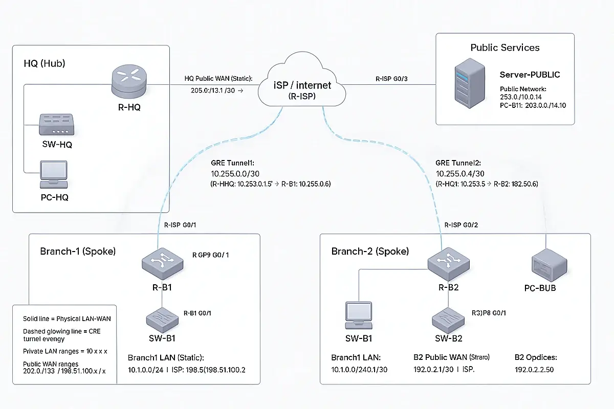
Scenario: HQ (Hub) + 2 Branches (Spokes) are “remote” and connect to the Internet (ISP) using static public IPs. Private LANs communicate via GRE tunnels over the Internet (simulation-friendly in Packet Tracer). NAT (optional) lets LAN PCs reach a “public server”.
1) Topology you will build (devices)
Required devices
- 4 Routers
- R-ISP (Internet provider)
- R-HQ (Hub)
- R-B1 (Branch 1)
- R-B2 (Branch 2)
- 3 Switches (2960)
- SW-HQ, SW-B1, SW-B2
- 3 PCs
- PC-HQ, PC-B1, PC-B2
- 1 Public Server
- Server-PUBLIC
Physical layout suggestion
- Left: HQ site
- Center: ISP router
- Right/bottom-right: Branch1, Branch2
- Top-right: Public Server network
2) Cabling (use Copper Straight-Through)
LAN cabling
- R-HQ G0/0 → SW-HQ F0/1
- PC-HQ Fa0 → SW-HQ F0/2
- R-B1 G0/0 → SW-B1 F0/1
- PC-B1 Fa0 → SW-B1 F0/2
- R-B2 G0/0 → SW-B2 F0/1
- PC-B2 Fa0 → SW-B2 F0/2
WAN (“Internet”) cabling
- R-HQ G0/1 → R-ISP G0/0
- R-B1 G0/1 → R-ISP G0/1
- R-B2 G0/1 → R-ISP G0/2
Public server cabling
- Server-PUBLIC Fa0 → R-ISP G0/3
Important: Interface names vary by router model. If your router doesn’t have the exact ports (G0/0, G0/1, etc.), use:
show ip interface brief on each router and adjust the interface names accordingly.
Below is a fully detailed, step-by-step guide to build the WAN “Internet + Static Public IP + 2 Branches” environment in Cisco Packet Tracer, exactly like your lab design (R-HQ hub, R-B1 and R-B2 spokes, R-ISP internet, public server, GRE tunnels). This is written so you can follow it click-by-click.
Step 0 — Create a new lab file
- Open Cisco Packet Tracer.
- Click File → New.
- Click File → Save As…
- Name it: HubSpoke_Internet_StaticIP_2Branches.pkt
- Save.
Step 1 — Place the devices on the workspace
1.1 Add Routers (4)
- Bottom-left panel → click Network Devices.
- Click Routers.
- Drag 4 routers onto the workspace.
Name/Role
- One will be R-ISP
- One will be R-HQ
- One will be R-B1
- One will be R-B2
Router model tip: Choose a router with at least 2 GigabitEthernet ports (commonly 1941/2911 depending on your PT). We need LAN + WAN per site.
1.2 Add Switches (3)
- Bottom-left panel → Network Devices → Switches
- Drag 3 switches (e.g., 2960) onto the workspace.
- SW-HQ, SW-B1, SW-B2
1.3 Add PCs (3)
- Bottom-left panel → End Devices
- Drag 3 PCs.
- PC-HQ, PC-B1, PC-B2
1.4 Add a Public Server (1)
- Bottom-left panel → End Devices
- Drag 1 Server onto the workspace.
- Server-PUBLIC
Step 2 — Rename every device (prevents mistakes)
Do this for each router/switch/PC/server:
- Click the device.
- Go to Config tab.
- Find Display Name (or the device name field).
- Change it to the correct name.
Rename exactly:
- Routers: R-ISP, R-HQ, R-B1, R-B2
- Switches: SW-HQ, SW-B1, SW-B2
- PCs: PC-HQ, PC-B1, PC-B2
- Server: Server-PUBLIC
Step 3 — Cable the LANs (Copper Straight-Through)
3.1 Select correct cable type
- Click Connections (lightning bolt icon).
- Choose Copper Straight-Through.
3.2 HQ LAN cabling
- Click R-HQ → choose GigabitEthernet0/0 (or G0/0).
- Click SW-HQ → choose FastEthernet0/1 (or F0/1).
- Click PC-HQ → choose FastEthernet0.
- Click SW-HQ → choose FastEthernet0/2.
3.3 Branch1 LAN cabling
- R-B1 G0/0 → SW-B1 F0/1
- PC-B1 Fa0 → SW-B1 F0/2
3.4 Branch2 LAN cabling
- R-B2 G0/0 → SW-B2 F0/1
- PC-B2 Fa0 → SW-B2 F0/2
If your router ports are not G0/0, pick the first available LAN-capable Ethernet port shown.
Step 4 — Cable the WAN “Internet” links (Copper Straight-Through)
We will connect each site router to the ISP router.
4.1 HQ to ISP
- Choose Copper Straight-Through
- Click R-HQ → choose G0/1
- Click R-ISP → choose G0/0
4.2 Branch1 to ISP
- Click R-B1 → choose G0/1
- Click R-ISP → choose G0/1
4.3 Branch2 to ISP
- Click R-B2 → choose G0/1
- Click R-ISP → choose G0/2
4.4 Public Server to ISP
- Click Server-PUBLIC → choose FastEthernet0
- Click R-ISP → choose G0/3 (or any extra Ethernet port)
If your ISP router doesn’t have G0/3, use any free Ethernet interface and adjust the config later.
Step 5 — Prepare the IP plan (use exactly these values)
5.1 Private LAN subnets
- HQ LAN: 10.0.0.0/24
- R-HQ G0/0 = 10.0.0.1
- PC-HQ = 10.0.0.50, GW 10.0.0.1
- Branch1 LAN: 10.1.0.0/24
- R-B1 G0/0 = 10.1.0.1
- PC-B1 = 10.1.0.50, GW 10.1.0.1
- Branch2 LAN: 10.2.0.0/24
- R-B2 G0/0 = 10.2.0.1
- PC-B2 = 10.2.0.50, GW 10.2.0.1
5.2 Public WAN links (static public IPs)
- HQ ↔ ISP: 203.0.113.0/30
- HQ: 203.0.113.1
- ISP: 203.0.113.2
- B1 ↔ ISP: 198.51.100.0/30
- B1: 198.51.100.1
- ISP: 198.51.100.2
- B2 ↔ ISP: 192.0.2.0/30
- B2: 192.0.2.1
- ISP: 192.0.2.2
5.3 Public services network
- Public network: 203.0.114.0/24
- ISP: 203.0.114.1
- Server: 203.0.114.10, GW 203.0.114.1
5.4 GRE overlay tunnel networks
- Tunnel1 (HQ↔B1): 10.255.0.0/30
- HQ: 10.255.0.1
- B1: 10.255.0.2
- Tunnel2 (HQ↔B2): 10.255.0.4/30
- HQ: 10.255.0.5
- B2: 10.255.0.6
Step 6 — Configure R-ISP (the “Internet” router)
- Click R-ISP
- Go to CLI
- Press Enter once
- Paste this (adjust interface names if different):
enable
conf t
hostname R-ISP
no ip domain-lookup
interface g0/0
ip address 203.0.113.2 255.255.255.252
no shutdown
interface g0/1
ip address 198.51.100.2 255.255.255.252
no shutdown
interface g0/2
ip address 192.0.2.2 255.255.255.252
no shutdown
interface g0/3
ip address 203.0.114.1 255.255.255.0
no shutdown
end
wr
✅ Verify interfaces:
show ip interface brief
Step 7 — Configure R-HQ (Hub)
- Click R-HQ → CLI
- Paste:
enable
conf t
hostname R-HQ
no ip domain-lookup
interface g0/0
ip address 10.0.0.1 255.255.255.0
no shutdown
interface g0/1
ip address 203.0.113.1 255.255.255.252
no shutdown
ip route 0.0.0.0 0.0.0.0 203.0.113.2
end
wr
7.1 Create GRE tunnels on HQ
Still on R-HQ CLI, paste:
enable
conf t
interface tunnel1
ip address 10.255.0.1 255.255.255.252
tunnel source g0/1
tunnel destination 198.51.100.1
no shutdown
interface tunnel2
ip address 10.255.0.5 255.255.255.252
tunnel source g0/1
tunnel destination 192.0.2.1
no shutdown
ip route 10.1.0.0 255.255.255.0 tunnel1
ip route 10.2.0.0 255.255.255.0 tunnel2
end
wr
✅ Verify:
show ip interface brief
show interface tunnel1
show interface tunnel2
Step 8 — Configure R-B1 (Branch 1)
- Click R-B1 → CLI
- Paste:
enable
conf t
hostname R-B1
no ip domain-lookup
interface g0/0
ip address 10.1.0.1 255.255.255.0
no shutdown
interface g0/1
ip address 198.51.100.1 255.255.255.252
no shutdown
ip route 0.0.0.0 0.0.0.0 198.51.100.2
end
wr
8.1 Create GRE tunnel to HQ + routes
Paste:
enable
conf t
interface tunnel1
ip address 10.255.0.2 255.255.255.252
tunnel source g0/1
tunnel destination 203.0.113.1
no shutdown
ip route 10.0.0.0 255.255.255.0 10.255.0.1
ip route 10.2.0.0 255.255.255.0 10.255.0.1
end
wr
✅ Verify:
show interface tunnel1
show ip route
Step 9 — Configure R-B2 (Branch 2)
- Click R-B2 → CLI
- Paste:
enable
conf t
hostname R-B2
no ip domain-lookup
interface g0/0
ip address 10.2.0.1 255.255.255.0
no shutdown
interface g0/1
ip address 192.0.2.1 255.255.255.252
no shutdown
ip route 0.0.0.0 0.0.0.0 192.0.2.2
end
wr
9.1 Create GRE tunnel to HQ + routes
Paste:
enable
conf t
interface tunnel2
ip address 10.255.0.6 255.255.255.252
tunnel source g0/1
tunnel destination 203.0.113.1
no shutdown
ip route 10.0.0.0 255.255.255.0 10.255.0.5
ip route 10.1.0.0 255.255.255.0 10.255.0.5
end
wr
✅ Verify:
show interface tunnel2
show ip route
Step 10 — Configure PCs and the Public Server (GUI steps)
10.1 PC-HQ
- Click PC-HQ
- Desktop → IP Configuration
- Set:
- IP Address: 10.0.0.50
- Subnet Mask: 255.255.255.0
- Default Gateway: 10.0.0.1
10.2 PC-B1
- IP: 10.1.0.50
- Mask: 255.255.255.0
- Gateway: 10.1.0.1
10.3 PC-B2
- IP: 10.2.0.50
- Mask: 255.255.255.0
- Gateway: 10.2.0.1
10.4 Server-PUBLIC
- Click Server-PUBLIC
- Desktop → IP Configuration
- Set:
- IP Address: 203.0.114.10
- Subnet Mask: 255.255.255.0
- Default Gateway: 203.0.114.1
Step 11 — Verify WAN environment (must pass)
11.1 Check all router interfaces are up/up
On each router:
show ip interface brief
11.2 Test public WAN reachability (each site to ISP)
From R-HQ:
ping 203.0.113.2
From R-B1:
ping 198.51.100.2
From R-B2:
ping 192.0.2.2
11.3 Verify GRE tunnels are up (overlay)
On R-HQ:
show interface tunnel1
show interface tunnel2
Expected: Tunnel is up, line protocol is up
11.4 Test private LAN-to-LAN (over Internet via GRE)
From PC-B1 → Command Prompt:
- ping 10.0.0.50
- ping 10.2.0.50
From PC-B2:
- ping 10.0.0.50
- ping 10.1.0.50
If these succeed → your “remote branches over Internet with static public IPs” WAN environment is correctly built.
Step 12 (Optional but realistic) Add NAT so PCs can reach Public Server
This simulates real internet browsing from private LANs.
12.1 NAT on R-HQ
On R-HQ:
enable
conf t
access-list 1 permit 10.0.0.0 0.0.0.255
interface g0/0
ip nat inside
interface g0/1
ip nat outside
ip nat inside source list 1 interface g0/1 overload
end
wr
12.2 NAT on R-B1
On R-B1:
enable
conf t
access-list 1 permit 10.1.0.0 0.0.0.255
interface g0/0
ip nat inside
interface g0/1
ip nat outside
ip nat inside source list 1 interface g0/1 overload
end
wr
12.3 NAT on R-B2
On R-B2:
enable
conf t
access-list 1 permit 10.2.0.0 0.0.0.255
interface g0/0
ip nat inside
interface g0/1
ip nat outside
ip nat inside source list 1 interface g0/1 overload
end
wr
12.4 NAT test from PCs
From any PC:
- ping 203.0.114.10
Check NAT translations (optional):
show ip nat translations
show ip nat statistics
Step 13 — Save your lab properly
- Click File → Save
- (Recommended) Save a copy as a milestone:
- File → Save As…
- HubSpoke_StaticIP_GRE_NAT_v1.pkt